RVT_ELEC_01101 Latest Test Discount & RVT_ELEC_01101 Latest Exam Question
Wiki Article
BTW, DOWNLOAD part of ExamsReviews RVT_ELEC_01101 dumps from Cloud Storage: https://drive.google.com/open?id=1kYszYYRn90e5DAUBfvIPsHCGx6_HJYqB
ExamsReviews Autodesk RVT_ELEC_01101 pdf questions have been marked as the topmost source for the preparation of RVT_ELEC_01101 new questions by industry experts. These questions cover every topic in the exam, and they have been verified by Autodesk professionals. Moreover, you can download the Autodesk Certified Professional in Revit for Electrical Design (RVT_ELEC_01101) pdf questions demo to get a better analysis of the exam. By practicing with these questions, you can assess your preparation for the Autodesk RVT_ELEC_01101 new questions.
Autodesk RVT_ELEC_01101 Exam copyright Topics:
| Topic | Details |
|---|---|
| Topic 1 |
|
| Topic 2 |
|
| Topic 3 |
|
| Topic 4 |
|
| Topic 5 |
|
>> RVT_ELEC_01101 Latest Test Discount <<
Well-Prepared RVT_ELEC_01101 Latest Test Discount & Complete Autodesk Certification Training - Professional Autodesk Autodesk Certified Professional in Revit for Electrical Design
Our company is your ally in achieving your targeted certification, providing you easy and interactive RVT_ELEC_01101 exam copyright. You can totally count on us as we are good at help you get the success on your coming exam. We will always stand by your on your way for the certification as we work as 24/7 online. If you have any question, you can find help from us on the RVT_ELEC_01101 Study Guide. And our RVT_ELEC_01101 learning questions are well-written to be understood by the customers all over the world.
Autodesk Certified Professional in Revit for Electrical Design Sample Questions (Q62-Q67):
NEW QUESTION # 62
An electrical designer is trying to adjust the scale of a view. All icons on the View Control Bar are dimmed (not enabled). How should the designer make the view scale editable only for this view?
- A. Edit the assigned view template.
- B. Set the view template to <None>
- C. Right-click on the scale and select <Activate>.
- D. Duplicate the view with Detailing.
Answer: B
Explanation:
When all icons on the View Control Bar are dimmed (disabled), including the View Scale, it typically means the view is being controlled by a View Template. View templates apply standardized settings-such as scale, discipline, detail level, and more-across multiple views to ensure consistency. However, these templates can lock certain parameters, including the view scale, preventing manual changes.
According to Revit Electrical Design standards:
"If a view is governed by a View Template, properties such as view scale may be locked and appear dimmed in the View Control Bar. To regain control and allow changes like adjusting the view scale, the view template must be removed. This is done by setting the View Template to <None> in the Properties Palette." Steps:
Select the view in question.
Open the Properties Palette.
Locate the View Template parameter.
Set it to <None>.
Now the View Control Bar becomes active and the scale can be changed freely.
Clarification of Other Options:
B (Edit the assigned view template): Changes apply to all views using that template, not just the one.
C (Duplicate the view with Detailing): Creates a copy but doesn't resolve template restrictions.
D (Right-click on the scale and select <Activate>): This is not a valid method in Revit.
Reference:
This explanation aligns with the View Template behavior documented in Revit MEP and Electrical modeling workflows.
NEW QUESTION # 63
Refer to exhibit.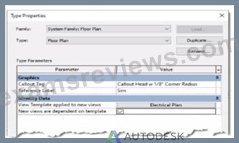
An electrical designer is reviewing the Type Properties for a floor plan view. How will the view behove when creating a new floor plan?
- A. When duplicating a floor plan view of any type, the Electrical Plan view template will be assigned to the new floor plan view.
- B. The Electrical Plan view template will be assigned to a new floor plan view created with the Floor Plan tool with the Floor Plan type selected
- C. Creating a new floor plan view using the Floor Plan tool with the Floor Plan type selected will create a new Electrical Plan view template.
- D. A new floor plan view created by duplicating a floor plan view of the Floor Plan type will be duplicated as a dependent view.
Answer: B
Explanation:
The exhibit shown displays the Type Properties dialog box for a System Family: Floor Plan view type. Within the "Identity Data" group, there are two critical parameters that govern the behavior of new views created from this view type:
"View Template applied to new views"
"New views are dependent on template"
According to Autodesk Revit's documentation in the Revit MEP User's Guide (Chapter 48 "Views and View Templates" and Chapter 49 "Preparing Construction Documents"):
"When a view template is assigned to a view type through the Type Properties dialog, any new view created from that view type automatically receives the defined view template. This ensures consistent visibility, graphics, and discipline settings for all new views." In this image, the parameter "View Template applied to new views" is set to Electrical Plan, and "New views are dependent on template" is checked. This means that any new floor plan created using this type will automatically have the Electrical Plan template applied, and the view will be dependent on that template, meaning it inherits all its visibility and annotation control settings.
This ensures that all electrical floor plan views generated are standardized and visually consistent, a fundamental practice in Revit Electrical Design workflows, as described in the Smithsonian Facilities Revit Template User's Guide:
"Assigning a default view template to a view type (e.g., Electrical Plan) ensures every new view created follows organizational and graphical standards without manual setup." Option A matches this behavior exactly.
Option B is incorrect** because Revit does not create a new template automatically.
Option C is incorrect** because duplication of an existing view does not reassign templates by type.
Option D is incorrect** because dependent view creation requires a specific "Duplicate as Dependent" command, not this setting.
References:
Autodesk Revit MEP User's Guide - Chapter 48 "Views and View Templates," pp. 1112-1115 Smithsonian Facilities Revit Template User's Guide - Section 2.8.1 "View Types and View Templates," p. 30 Autodesk Revit Electrical Design Essentials - View Template Application and Management Section
NEW QUESTION # 64
An electrical designer is adding lights to a project model. The coiling grids arc located in a linked Revit model. How are these lights affected if the grid patterns move?
- A. The lights move with the pattern if they are alignment-locked to the ceiling and hosted.
- B. The lights do not follow grid pattern movement unless they are non-hosted.
- C. The lights do not move with the pattern but will stay associated with the ceiling if hosted
- D. The lights move with the pattern if they are defined as ceiling-hosted types.
Answer: C
Explanation:
When working in Autodesk Revit for MEP Electrical Design, lighting fixtures can be either hosted (such as ceiling-hosted or wall-hosted) or non-hosted. The movement of lighting fixtures in relation to linked model elements-like ceiling grids-is determined by the hosting condition and alignment constraints applied to those elements.
According to the Revit MEP User's Guide (Chapter 24 "Ceilings" and Chapter 50 "Rendering"), a ceiling is a level-based element. You can create it on a specified level and host ceiling-based families such as lighting fixtures. When a ceiling is modified or repositioned, the hosted lighting fixtures will move with the ceiling itself, maintaining their relationship to the host surface. However, when ceiling grid patterns are changed or moved in a linked Revit model, the movement of those grid patterns does not automatically propagate to hosted elements in the electrical model unless those elements are directly linked or constrained to a movable reference plane.
As described:
"Ceilings are level-based elements... When you create a ceiling, you can host components such as lighting fixtures on its face. Hosted elements remain associated with their host even if the ceiling is modified." And further in the glossary section:
"Rehost: To move a component from one host to another. For example, you can use the Pick New Host tool to move a window from one wall to another wall." This confirms that a hosted light fixture maintains its attachment to the host element (the ceiling) but not to the grid pattern itself. Grid movement within a linked ceiling model does not alter the position of lights unless they are manually re-hosted or alignment-locked directly to a specific geometry within the host model.
Therefore, the correct interpretation is that when ceiling grid patterns move within a linked Revit model, the lights placed in the electrical model do not follow the grid pattern movement automatically. They remain stationary relative to the ceiling surface, provided they are hosted correctly.
This behavior reflects Revit's parametric relationships - "hosted elements maintain dependency only on their host, not on graphical references like grids unless locked via constraints." References:
Autodesk Revit MEP User's Guide, Chapter 24 "Ceilings", pp. 579-583
Autodesk Revit MEP User's Guide, Chapter 50 "Rendering" (Lighting Fixtures and Hosts) Autodesk Revit Glossary: "Rehost" definition, p. 2037 Revit Electrical Design Parametric Model Behavior - Revit MEP Essentials
NEW QUESTION # 65
Refer to exhibits.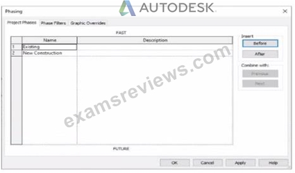
An electrical designer models an existing receptacle on an existing wall that the architect has indicated to be demolished.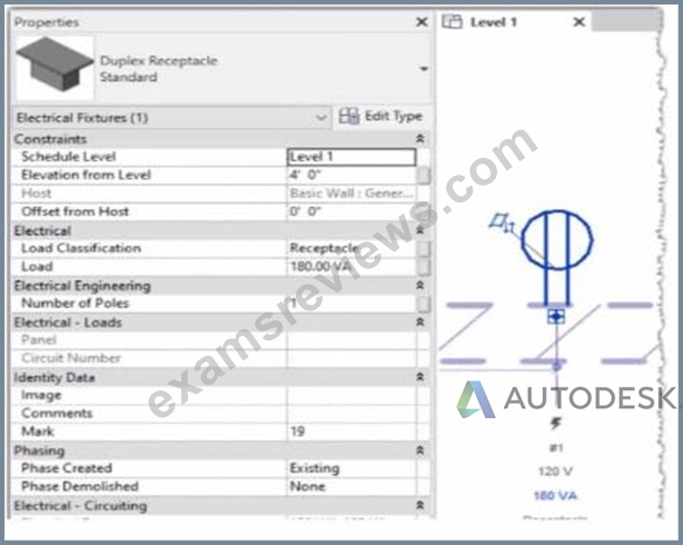
The view is intended to show demolition, and the view's Phase is set to New Construction. How should the designer indicate that the receptacle must also be demolished?
- A. Set the receptacle parameter Phase Demolished to Demolition.
- B. Set the receptacle parameter Phase Demolished to New Construction.
- C. Set the receptacle's type parameter Match Phasing to Host.
- D. Add a Demolition phase, then set the receptacle parameter Phase Demolished to Demolition.
Answer: B
Explanation:
In Autodesk Revit, phasing allows designers to track existing, demolished, and new elements across different project stages. Every model element includes two key phasing parameters:
Phase Created - defines when the element was built or introduced.
Phase Demolished - defines when the element is removed or demolished.
In the provided exhibits:
The project contains two phases: Existing and New Construction.
The receptacle's Phase Created parameter is set to Existing, indicating it belongs to the pre-existing building condition.
The architectural wall hosting the receptacle is to be demolished during New Construction.
When a view's Phase is set to New Construction and its Phase Filter is configured to show demolition, only elements whose Phase Demolished equals New Construction will appear as to be demolished. Therefore, the electrical designer must set the receptacle's Phase Demolished value to New Construction so that it graphically displays as a demolished element in the demolition plan.
As explained in the Autodesk Revit MEP User's Guide - Phasing and Coordination:
"Elements created in one phase and demolished in a subsequent phase must have their 'Phase Demolished' parameter set to that later phase to display properly in demolition views." Thus, to correctly coordinate with the demolition of its host wall, the receptacle must be flagged for demolition during New Construction.
NEW QUESTION # 66
An electrical designer receives an architectural model and links it into the electrical model.
The designer wants to use the Copy/Monitor tool to copy the exact electrical fixtures created by the architect.
The designer also wants the software to automatically detect new electrical fixtures added to the architectural model.
Select the correct coordination settings from the drop-down lists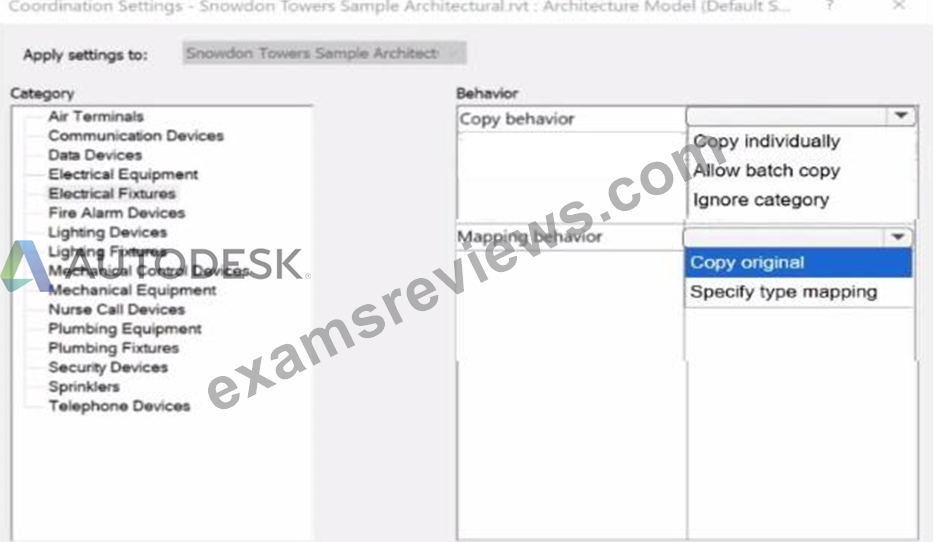
Answer:
Explanation: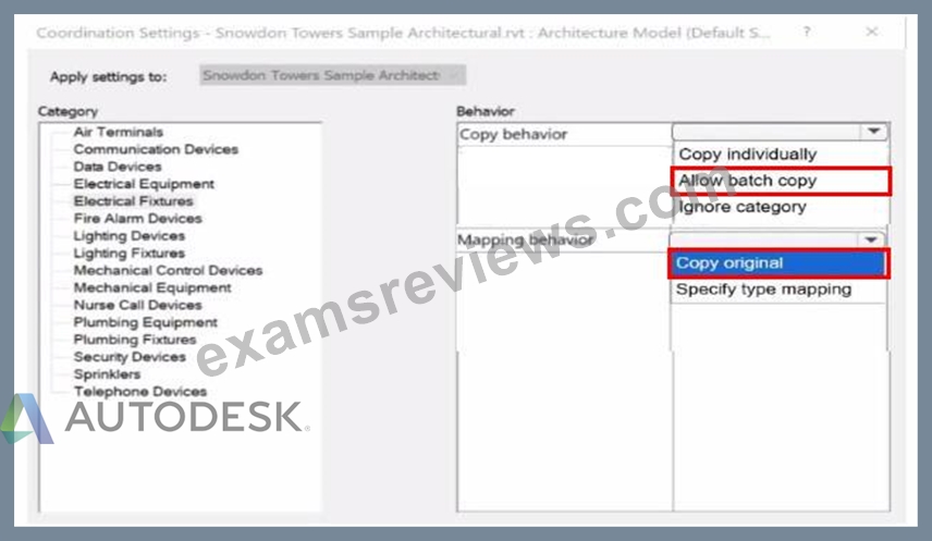
NEW QUESTION # 67
......
To avoid this situation, we recommend you RVT_ELEC_01101 real dumps. This product contains everything you need to crack the RVT_ELEC_01101 certification exam on the first attempt. By choosing ExamsReviews's updated dumps, you don't have to worry about appearing in the Autodesk Certified Professional in Revit for Electrical Design (RVT_ELEC_01101) certification exam. ExamsReviews Autodesk RVT_ELEC_01101 Dumps are enough to get you through the Autodesk Certified Professional in Revit for Electrical Design (RVT_ELEC_01101) actual exam on the first try.
RVT_ELEC_01101 Latest Exam Question: https://www.examsreviews.com/RVT_ELEC_01101-pass4sure-exam-review.html
- Sample RVT_ELEC_01101 Questions Answers ???? Sample RVT_ELEC_01101 Questions Answers ???? RVT_ELEC_01101 Latest Dumps Book ???? Search for ⇛ RVT_ELEC_01101 ⇚ and download it for free on 《 www.examcollectionpass.com 》 website ????RVT_ELEC_01101 Test Testking
- RVT_ELEC_01101 Cost Effective Dumps ???? Training RVT_ELEC_01101 Online ❗ RVT_ELEC_01101 Valid Test Fee ???? Search on ▶ www.pdfvce.com ◀ for 【 RVT_ELEC_01101 】 to obtain exam materials for free download ????RVT_ELEC_01101 Test Testking
- Pass Guaranteed Autodesk - High Pass-Rate RVT_ELEC_01101 Latest Test Discount ???? Go to website ( www.practicevce.com ) open and search for ☀ RVT_ELEC_01101 ️☀️ to download for free ℹRVT_ELEC_01101 New Real Test
- Quiz Autodesk - RVT_ELEC_01101 - Valid Autodesk Certified Professional in Revit for Electrical Design Latest Test Discount ???? Search for { RVT_ELEC_01101 } and download it for free immediately on ⇛ www.pdfvce.com ⇚ ????RVT_ELEC_01101 Clearer Explanation
- RVT_ELEC_01101 Desktop Practice Exam Software ⬅ Search for 【 RVT_ELEC_01101 】 and download exam materials for free through ⇛ www.verifieddumps.com ⇚ ????RVT_ELEC_01101 New Real Test
- RVT_ELEC_01101 New Real Test ⏮ Guaranteed RVT_ELEC_01101 Questions Answers ???? New RVT_ELEC_01101 Dumps ???? Open ( www.pdfvce.com ) and search for ▶ RVT_ELEC_01101 ◀ to download exam materials for free ????RVT_ELEC_01101 Latest Dumps Book
- RVT_ELEC_01101 Cost Effective Dumps ???? Latest Test RVT_ELEC_01101 Experience ???? RVT_ELEC_01101 Accurate Prep Material ???? Search for “ RVT_ELEC_01101 ” and easily obtain a free download on ⇛ www.examcollectionpass.com ⇚ ????Latest RVT_ELEC_01101 Exam Fee
- Updated RVT_ELEC_01101 Testkings ???? RVT_ELEC_01101 Practice Tests ???? Sample RVT_ELEC_01101 Questions Answers ???? Open { www.pdfvce.com } enter ( RVT_ELEC_01101 ) and obtain a free download ????RVT_ELEC_01101 Certification
- RVT_ELEC_01101 Valid Test Fee ???? Exam RVT_ELEC_01101 Vce Format ???? Sample RVT_ELEC_01101 Questions Answers ???? Open 《 www.prepawaypdf.com 》 and search for ➠ RVT_ELEC_01101 ???? to download exam materials for free ⭐RVT_ELEC_01101 New Real Test
- RVT_ELEC_01101 Latest Dumps Book ???? RVT_ELEC_01101 Test Online ???? RVT_ELEC_01101 Test Testking ???? Easily obtain free download of ▶ RVT_ELEC_01101 ◀ by searching on ➤ www.pdfvce.com ⮘ ????Exam RVT_ELEC_01101 Vce Format
- RVT_ELEC_01101 Clearer Explanation ???? RVT_ELEC_01101 Vce Torrent ???? Sample RVT_ELEC_01101 Questions Answers ???? Search for ⏩ RVT_ELEC_01101 ⏪ and obtain a free download on ⇛ www.examdiscuss.com ⇚ ????RVT_ELEC_01101 Vce Torrent
- digibookmarks.com, marleyizaf057894.theobloggers.com, rorymgfo259393.kylieblog.com, liviaxmaq526824.blogars.com, amiesyhe958547.empirewiki.com, larissairev417667.fare-blog.com, oisizfcd451738.governor-wiki.com, singnalsocial.com, jayapjwe834800.wikievia.com, ianfuuh654579.blogripley.com, Disposable vapes
P.S. Free 2026 Autodesk RVT_ELEC_01101 dumps are available on Google Drive shared by ExamsReviews: https://drive.google.com/open?id=1kYszYYRn90e5DAUBfvIPsHCGx6_HJYqB
Report this wiki page